ESP8266 WiFi 5V 1 Channel Relay Module Good Quality
$ 2.37
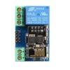
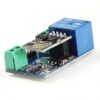
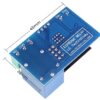
DescriptionGeneral Info : Onboard ESP8266 WIFI module, AP mode can be connected at the same time 5 clientThe module has two ways to work: (i) mobile phone directly mounted on the WIFI module; (ii) mobile phone and WIFI module also carried on the router.How to use :Onboard ESP8266 WIFI module has three operating modes: STA (client), AP (hot), STA AP (client hot), according to the work of the module to select the corresponding WIFI module mode of operation TheThe module needs to use the serial debugging software on the computer and USB to TTL module to send AT commands to configure the WIFI module, USB to TTL module RX, TX, GND pin, then the module on the TX, RX, GND pin, IN , IN – 5V power supply.Usage Instructions1) Hardware Connection: Insert the pre-programmed ESP-01/01S module into the onboard 2×4 pin female header (as shown in the diagram below).2) Power Supply : Connect a DC 5V-12V power source to the module, with the positive terminal to VCC and the negative terminal to GND.3) Mobile WiFi Connection : Open your phone’s WLAN settings, search for and connect to the ESP8266-XXXX hotspot (default password: 12345678).4) Launch Control APP : Run the pre-installed ESP8266 Controller application on your Android phone.5) Configure IP Address : Enter the default IP address: 192.168.1.1 in the APP to remotely control the relay switch via your phone.Transmission distance:Open environment, the mobile phone mounted on the WIFI module when the maximum transmission distance of 400m.When the WiFI module and mobile phone at the same time carried on the router when the transmission distance according to the router’s signal weakly;Board function description : IN , IN-: 5V power input; TX, RX, GND: Serial debug pin;Onboard the ESP8266 WIFI module has three work modes: STA (client), AP (hot), the STA Ap( hot client), according to the workings of a module to the corresponding choice of WIFI module working mode. Module need before use serial debugging software and USB to TTL module send serial command was carried out on the WIFI module configuration (don’t power outages after configuration is complete, as some of the parameters of WIFI module cannot be saved when the power is cut off), mobile phone and WIFI module after establishing a network connection can use the phone APP control relay.Control Commands :When cell phone equipped with WiFi module sends commands in the following order: (The default baud rate 115200) AT CWMODE=2, namely AP mode is selected.AT RST, reset. AT CIPMUX=1, open multiple connections. AT CIPSERVER=1,8080, configure the TCP server, set the port. AT CIOBAUD=9600 set the baud rate to 9600. (working in relays to control the baud rate 9600). AT CIFSR to view the AP mode IP address, such as the APIP, “192.168.4.1”. Cell phone WIFI signal connection name starts with AI-THINKER or ESP8266. In the “TCP connection” address and port into the APP, such as 192.168.4.1 and 8080. Click on the grey box relays can be controlled.Features:Onboard Module: ESP8266 wifi module; in AP mode it can connect with 5 Clients at the same timeOperating Way: cellphone carried on wifi module; cellphone and wifi module carried on the same router, and use the APP to control relayDiode effusion protection.Short response time